Research & Development
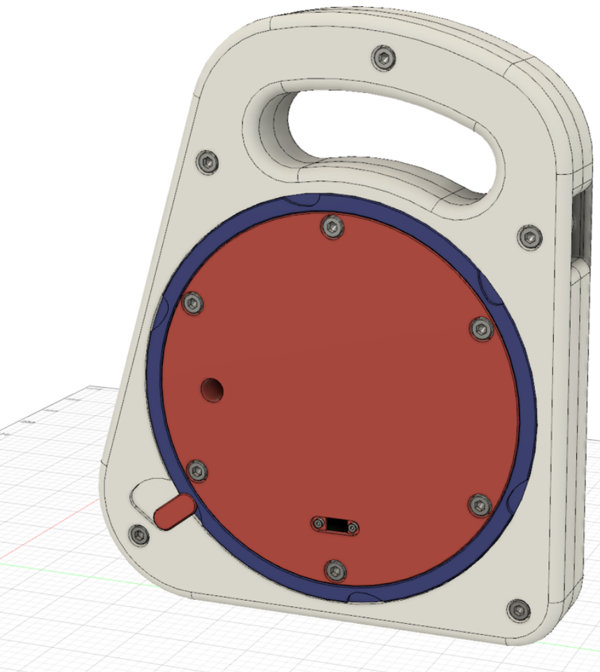
We constantly keep developing our own measurement technology and test facilities. We value robust and at the same time mobile equipment. All measured values are radio transmitted, saving weight and frustration with long cables. 3D printing plays an important role for us. Among other things, we use it to manufacture the cable reels for our oxygen probes, with all electronics packed tightly away inside the reel.
We also gained a lot of experience from the development of our mobile offgas hood. The challenge was to develop a design that could be transported by public means and at the same time proved to float reliably stable. And our dismountable, mobile test unit for the determination of alpha factors had us racking our brains on one or another detail. With success.
We'll be happy to support you, too, in developing solutions to meet your special requirements on field measurement equipment. From brainstorming to prototyping.
With our test facilities we also do examination of individual aerator elements. This includes testing of cleaning methods which supports our customers in maximizing the lifespan of their diffusers.
Data Evaluation, Continuous Balancing, Simulation
Data acquisition and data evaluation are two sides of the same coin. And of course we are capable of much more than the evaluation of our oxygen transfer tests. With many years of experience in the evaluation of wastewater treatment plant operational data we support our customers to gain maximum information about their plants.
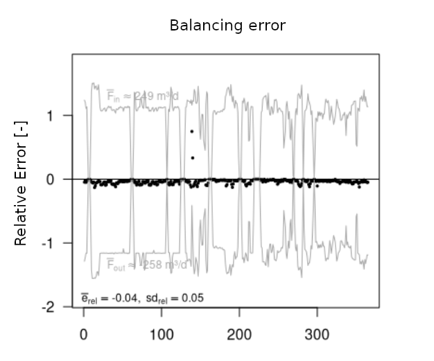
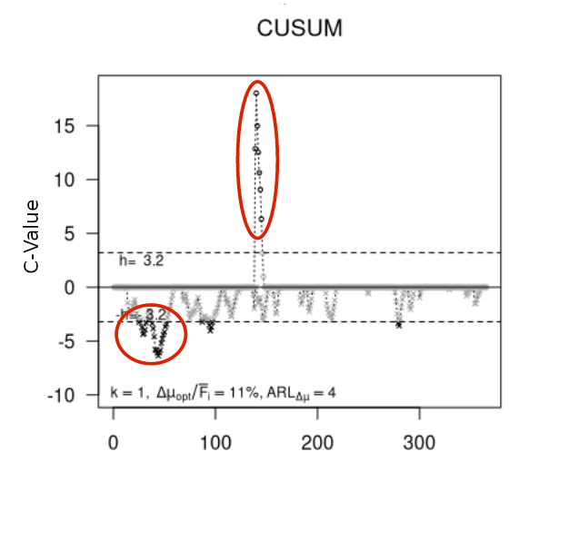
Doubting the reliability of your operational data? We might be the only team to master the method of continuous material flow balancing for wastewater treatment plants. This method allows early detection and therefore timely examination even of small systematic deviations in the measured data.
A wide variety of questions can be answered on the basis of plausible data. Are load increases permissible? When and for how long can aeration tanks be taken out of service? How to optimally deal with seasonal load variations? Might anaerobic sludge treatment be feasible for a particular (small) plant? We strive to answer such questions, often applying dynamic simulation based on proven models (Activated Sludge Model ASM, Anaerobic Digestion Model ADM).
Additional measurement services
Mainly in connection with our OTR measurements we also conduct a number of other measurements:
Flow measurements
For the point measurement of flow velocities we use an ADV (Acoustic Doppler Velocimeter). The usual purpose is the verification of flow velocity near the bottom of the tank. A safe location above the water level is required for mounting the measuring device.
Air flow measurements
For conventional rotary lobe compressors, we determine the air flow volume from the compressor speed and characteristics. For turbocompressors the internal air flow measurement has mostly proven reliable.
In case a separate measurement is required we perform it with a thermoanemometer. A suitable measuring location in the air distribution system is necessary.